US PATENT 10,265,176 B2
METHOD OF FUSING A SACROILIAC JOINT WITH AN IMPLANT VIA POSTERIOR ACCESS
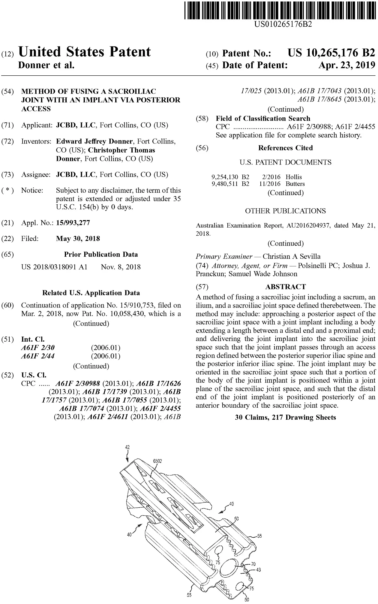
A method of fusing a sacroiliac joint including a sacrum, an ilium, and a sacroiliac joint space defined therebetween. The method may include: approaching a posterior aspect of the sacroiliac joint space with a joint implant including a body extending a length between a distal end and a proximal end; and delivering the joint implant into the sacroiliac joint space such that the joint implant passes through an access region defined between the posterior superior iliac spine and the posterior inferior iliac spine. The joint implant may be oriented in the sacroiliac joint space such that a portion of the body of the joint implant is positioned within a joint plane of the sacroiliac joint space, and such that the distal end of the joint implant is positioned posteriorly of an anterior boundary of the sacroiliac joint space.
CLAIMS
1. A method of fusing a sacroiliac joint comprising a sacrum, an ilium, and a sacroiliac joint space defined therebetween, the ilium comprising a posterior superior iliac spine and a posterior inferior iliac spine, the method comprising:
a) approaching a posterior aspect of the sacroiliac joint space with a joint implant assembly comprising an implant body extending a length between a distal end portion and a proximal end portion, a sacral cylindrical body supported by the proximal end portion on a sacral side of the joint implant, and an iliac cylindrical body supported by the proximal end portion on an iliac side of the joint implant, the implant body comprising a rectangular elongate body extending along the length and supported by the proximal end portion and having a passageway extending transversely therethrough, the rectangular elongate body positioned and extending between the iliac and sacral cylindrical bodies; and
b) delivering the joint implant assembly into the sacroiliac joint space such that the implant body passes through an access region defined between the posterior superior iliac spine and the posterior inferior iliac spine, the implant body being oriented in the sacroiliac joint space such that: a portion of the implant body is positioned within a joint plane of the sacroiliac joint space, the portion including at least a portion of the passageway; the rectangular elongate body is positioned generally perpendicular to the joint plane; and, the sacral cylindrical body is positioned within the sacrum and the iliac cylindrical body is positioned within the ilium.
2. The method of claim 1, wherein the sacral and iliac cylindrical bodies are threaded members.
3. The method of claim 2, further comprising rotating the threaded members into engagement with the sacrum and ilium.
4. The method of claim 1, wherein the sacral and iliac cylindrical bodies are barbed members.
5. The method of claim 4, further comprising driving the barbed members into engagement with the sacrum and ilium.
6. The method of claim 1, wherein the sacral and iliac cylindrical bodies are supported by a rectangular end cap defining the proximal end portion.
7. The method of claim 1, wherein delivering the joint implant assembly into the sacroiliac joint space comprises separately delivering into the sacroiliac joint space the implant body, the sacral iliac cylindrical body, and the iliac cylindrical body.
8. The method of claim 1, wherein delivering the joint implant assembly into the sacroiliac joint space comprises first delivering the implant body into the sacroiliac joint, followed by delivering the sacral and iliac cylindrical bodies into the sacrum and ilium, respectively.
9. The method of claim 1, wherein the implant body, the sacral cylindrical body, and the iliac cylindrical body are separate components of the joint implant assembly.
10. A method of fusing a sacroiliac joint comprising a sacrum, an ilium, and a sacroiliac joint space defined therebetween and comprising a joint plane, the method comprising:
a) approaching a posterior aspect of the sacroiliac joint space with a joint implant in an alignment relative to the sacroiliac joint space, the joint implant comprising a body extending a length between a distal end portion and a proximal end portion, the body comprising a central longitudinal axis extending along the length, first, second, third and fourth wing members extending the length and joined together at an intersection that is aligned with the central longitudinal axis, the alignment of the joint implant relative to the sacroiliac joint space being where the central longitudinal axis of the joint implant is generally parallel with the joint plane; and
b) delivering the joint implant into the sacroiliac joint space in the alignment, the joint implant being oriented in the sacroiliac joint space such that: a portion of the body of the joint implant is positioned within the joint plane, at least one of the first, second, third or fourth wing members is positioned within the sacrum, and at least one of the first, second, third or fourth wing members is positioned within the ilium.
11. The method of claim 10, wherein the first, second, third, and fourth wing members are non-expanding, rigid members.
12. A method of fusing a sacroiliac joint comprising a sacrum, an ilium, and a sacroiliac joint space defined therebetween, the ilium comprising a posterior superior iliac spine and a posterior inferior iliac spine, the method comprising:
a) approaching the sacroiliac joint space with a joint implant comprising:
a length extending between a proximal end and a distal end;
an exterior surface extending the length and having a non-circular cross-section transverse to the length;
an interior surface opposite the exterior surface and extending the length, the interior surface defining an internal volume therein;
a wall thickness defined between the external surface and the interior surface;
a proximal opening extending into the internal volume;
a first wall section comprising a first plurality of struts arranged along the length and defining a first plurality of openings extending through the wall thickness; and
a second wall section comprising a second plurality of struts arranged along the length and defining a second plurality of opening extending through the wall thickness,
wherein the first and second plurality of struts are each arranged along lengths of the first and second wall sections, respectively, in a repeating strut pattern; and
b) delivering the joint implant into the sacroiliac joint space such that the joint implant passes through an access region defined between the posterior superior iliac spine and the posterior inferior iliac spine, the joint implant being oriented in the sacroiliac joint space such that a portion of the joint implant is positioned within a joint plane of the sacroiliac joint space.
13. The method of claim 12, wherein the step of approaching the sacroiliac joint space further comprises orienting the joint implant in an alignment relative to the sacroiliac joint space where the length of the joint implant is generally parallel with the joint plane, and wherein the step of delivering the joint implant further comprises delivering the joint implant in the alignment.
14. The method of claim 12, wherein the joint implant further comprises a keel extending along the length and extending outwardly away from the internal volume.
15. The method of claim 12, wherein the joint implant further comprises a bore extending through the exterior surface configured to receive an anchor therethrough.
16. The method of claim 15, further comprising: delivering the anchor through the bore.
17. The method of claim 1, wherein the rectangular elongate body comprises a length, a thickness defined between a top surface and a bottom surface and a width extending between the iliac and sacral cylindrical bodies which is greater than the thickness, and wherein, when the rectangular elongate body is positioned generally perpendicular to the joint plane, the width extends across the joint plane such that a first portion of the rectangular elongate body near the sacral cylindrical body is positioned within the sacrum and a second portion of the rectangular elongate body near the iliac cylindrical body is positioned within the ilium.
18. The method of claim 10, wherein the first, second, third and fourth wing members are arranged around the central longitudinal axis such that an angle between the first and third wing members is less than ninety degrees, an angle between the second and fourth wing members is less than ninety degrees, an angle between the first and fourth wing members is greater than ninety degrees and an angle between the second and third wing members is greater than ninety degrees.
19. The method of claim 10, wherein the second wing member is disposed in substantially opposed relation to the first wing member, the first and the second wing members forming a first plane, and wherein the third wing member is disposed in substantially opposed relation to the fourth wing member, the third and the fourth wing members forming a second plane.
20. The method of claim 19, wherein the second plane is disposed in a relation to the first plane such that they are separated by a pair of acute angles and a pair of obtuse angles.
21. The method of claim 19, wherein the second plane is disposed in a substantially orthogonal relation to the first plane.
22. The method of claim 21, wherein a first thickness of the first and second wing members is less than or greater than a second thickness of the third and fourth wing members.
23. The method of claim 22, wherein the first thickness is larger than the second thickness, and wherein a first height of the first and second wing members extending from the central longitudinal axis outward is larger than a second height of the third and fourth wing members extending from the central longitudinal axis outward.
24. The method of claim 10, wherein, when delivering the joint implant into the sacroiliac joint space in the alignment, the joint implant passes through an access region defined between a posterior superior iliac spine and a posterior inferior iliac spine.
25. The method of claim 24, wherein at least one of the first, second, third and fourth wing members is a non-expanding, rigid member.
26. The method of claim 10, wherein at least one of the first, second, third and fourth wing members comprises an osseointegratable material having pores configured to permit osseointegration therein.
27. The method of claim 26, wherein the pores of the osseointegratable material are interconnected.
28. The method of claim 10, wherein the body includes an aperture element extending through and transverse to the central longitudinal axis of the implant such that at least one of the first, second, third and fourth wing members is separated from at least one of the first, second, third and fourth wing members by the aperture element.
29. The method of claim 28, wherein the aperture element comprises a first aperture perimeter opposite a second aperture perimeter, and wherein at least one of the first and second aperture perimeters has an elongate shape including a perimeter length extending between the distal end portion and the proximal end portion which is greater than a perimeter height extending perpendicular to the perimeter length.
30. The method of claim 10, further comprising: accessing the sacroiliac joint space with a joint locator tool having a spatulate distal region; advancing an access tube over the joint locator tool; positioning at least one of a drill guide and a broach guide into the access tube; and, creating an implant receiving space by at least one of: i) drilling at least two spaced apart holes into at least one of the sacrum and the ilium, and ii) broaching a void into at least one of the sacrum and the ilium having a shape in cross-section to the length of the void that is non-circular.