US PATENT 9,333,090 B2 Systems for and methods of fusing a sacroiliac joint
Systems for and methods of fusing a sacroiliac joint are provided which include an implant assembly adapted to be inserted into the joint space defined by the bones of a sacrum and an ilium, a delivery tool and means for inserting the implant assembly into the joint. The implant assembly includes a body disposed intermediate distal and proximate end portions thereof and having oppositely disposed side members adapted to expandably engage the sacroiliac joint following insertion of the assembly into the joint space. A tool is provided and provides a means for placing the implant assembly adjacent the sacroiliac joint, inserting it into the joint space and expanding means are thereafter applied to expand the oppositely disposed side members into operative engagement with the joint.
CLAIMS
What is claimed is:
1. A method of fusing a sacroiliac joint including: bone material including a sacrum and an ilium, the sacrum including a lateral anterior curved boundary, the ilium including a posterior superior iliac spine having a posterior inferior overhang and a posterior inferior iliac spine; a joint space defined between the sacrum and the ilium and defining a joint plane; an extra-articular space including an extra-articular recess access region; and an articular region including a posterior inferior access region, a posterior boundary segment, an anterior-inferior corner, a caudal region, and a cranial region, the method comprising:
positioning an implant assembly adjacent the sacroiliac joint,
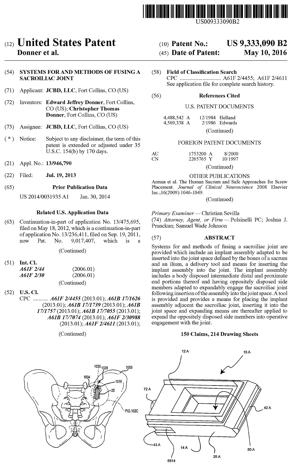
the implant assembly comprising a distal end portion, a proximal end portion, and a body portion extending between the distal and proximal end portions,
the body portion including
a first side member including a first opening and
a second side member including a second opening and oppositely disposed with the first side member such that the first and second openings are generally aligned to define a passageway extending across the body portion,
each of the first and second openings bounded by a fixed perimeter, each side member being structured and arranged to expandably engage the sacroiliac joint following insertion therein;
delivering the implant assembly into the sacroiliac joint via a posterior approach with a generally anterior trajectory of delivery,
the implant assembly being positioned in the joint space such that the first and second oppositely disposed side members generally oppose the sacrum and the ilium respectively; and
expanding the first and second oppositely disposed side members into operative engagement with the sacrum and the ilium.
2. The method of claim 1 wherein each of the side members includes a bone engaging surface having a plurality of ridges formed thereon structured and arranged to operatively engage the sacrum or the ilium in response to the expansion of the implant assembly.
3. The method of claim 1 wherein each of the side members includes a guide mechanism operatively connected thereto and adapted to guide the movement of the side member into operative engagement with the sacroiliac joint in response to the expansion of the side members.
4. The method of claim 1 wherein the each of the side members includes a sloped surface, the sloped surface being structured and arranged to operatively engage an actuating body configured to cause the oppositely disposed side members to expand.
5. The method of claim 1 wherein the body portion of the implant assembly includes an actuating body movably disposed in the proximal end of the implant assembly, the expanding step further comprising moving the actuating body into engagement with each of the oppositely disposed side members to expand them into engagement with the sacrum or the ilium.
6. The method of claim 5 wherein the actuating body includes a tapered surface.
7. The method of claim 4 wherein the body portion of the implant assembly includes the actuating body having a tapered surface movably disposed in the proximal end of the implant assembly, the expanding step further comprising moving the tapered surface of the actuating body into engagement with at least one of the sloped surfaces of the oppositely disposed side members to expand them into engagement with the sacrum and the ilium.
8. The method of claim 7 wherein the actuating body is at least partially threaded.
9. The method of claim 1 wherein the implant assembly is delivered into the joint space through the posterior inferior access region of the articular region of the sacroiliac joint.
10. The method of claim 1 wherein the posterior inferior access region has a superior end and an inferior end, the superior end being about 0 mm to about 40 mm inferior of the posterior inferior overhang of the posterior superior iliac spine.
11. The method of claim 10 wherein the inferior end is about at the intersection of the posterior inferior iliac spine and the lateral anterior curved boundary of the sacrum.
12. The method of claim 1 wherein the posterior inferior access region has a superior end and an inferior end, the inferior end being about at the intersection of the posterior inferior iliac spine and the lateral anterior curved boundary of the sacrum.
13. The method of claim 1 wherein the implant assembly is delivered into the joint space via a cranial access.
14. The method of claim 13 wherein the implant assembly is delivered into a cranial region of the sacroiliac joint.
15. The method of claim 1 wherein the implant assembly is delivered into the joint space via a caudal access.
16. The method of claim 15 wherein the implant assembly is delivered into a caudal region of the sacroiliac joint.
17. The method of claim 16 wherein the caudal region is bounded on an inferior side by an inferior boundary segment and on a superior side by a laterally extending portion of a posterior boundary segment.
18. The method of claim 1 wherein, in delivering the implant assembly into the joint space, a longitudinal edge of the body portion of the implant assembly is generally immediately adjacent an inferior sacroiliac joint space border while the distal end portion of the body portion is oriented towards: 1) an anterior sacroiliac joint space border; 2) a superior sacroiliac joint space border; or 3) somewhere between 1 and 2.
19. The method of claim 1 wherein the first and second openings maintain substantial alignment prior to and subsequent to delivery of the implant assembly into the sacroiliac joint.
20. The method of claim 1 wherein each of the side members includes a planar bone engaging surface.
21. The method of claim 20 wherein, when the implant assembly is positioned in the joint space, the planar bone engaging surfaces of the side members are generally parallel with the joint plane of the sacroiliac joint.
22. The method of claim 20 wherein the planar bone engaging surfaces remain planar when expanded into operative engagement with the sacrum and the ilium.
23. The method of claim 1 wherein each of the side members includes a bone engaging surface having at least one ridge formed thereon structured and arranged to operatively engage the sacrum or the ilium, the at least one ridges being in a fixed relation to the bone engaging surfaces.
24. The method of claim 1 wherein the expansion of the first and second side members is generally perpendicular to the joint plane.
25. The method of claim 1 wherein the expansion of the first and second side members is generally limited to being perpendicular to the joint plane.
26. The method of claim 1 wherein the expansion of the first and second side members is restrained to certain planes of expansion.
27. The method of claim 26 wherein the certain planes are planes generally perpendicular to the joint plane.
28. A method of fusing a sacroiliac joint including: bone material including a sacrum and an ilium, the sacrum including a lateral anterior curved boundary, the ilium including a posterior superior iliac spine having a posterior inferior overhang and a posterior inferior iliac spine; a joint space defined between the sacrum and the ilium and defining a joint plane; an extra-articular space including an extra-articular recess access region; and an articular region including a posterior inferior access region, a posterior boundary segment, an anterior-inferior corner, a caudal region, and a cranial region, the method comprising:
delivering an implant assembly non-transversely into the joint plane of the sacroiliac joint,
the implant assembly comprising a distal end portion, a proximal end portion, and a body portion extending along a longitudinal axis between the distal and proximal end portions,
the body portion including first and second oppositely disposed side members, a portion of each of the first and second side members configured to laterally expand relative to the longitudinal axis to engage the sacrum and ilium respectively following insertion therein,
the body portion further including a feature configured to constrain the lateral expansion to within a predetermined amount of expansion,
the implant assembly being positioned in the joint space such that the first and second oppositely disposed side members generally oppose the sacrum and the ilium respectively; and
expanding each of the first and second side members within the predetermined amount of expansion and into operative engagement with the sacrum and the ilium respectively.
29. The method of claim 28 wherein the first and second side members are expanded by an actuating body extending distally from the proximal end portion.
30. The method of claim 29 wherein the first and second side members include sloped surfaces on a proximal end, the actuating body configured to cause the proximal ends of the first and second side members to laterally expand when the actuating body extends distally.
31. The method of claim 29 wherein the actuating body is at least partially threaded.
32. The method of claim 28 wherein the implant assembly is delivered into the joint space through the posterior inferior access region of the articular region of the sacroiliac joint.
33. The method of claim 28 wherein the posterior inferior access region has a superior end and an inferior end, the superior end being about 0 mm to about 40 mm inferior of the posterior inferior overhang of the posterior superior iliac spine.
34. The method of claim 33 wherein the inferior end is about at the intersection of the posterior inferior, iliac spine and the lateral anterior curved boundary of the sacrum.
35. The method of claim 28 wherein the posterior inferior access region has a superior end and an inferior end, the inferior end being about at the intersection of the posterior inferior iliac spine and the lateral anterior curved boundary of the sacrum.
36. The method of claim 28 wherein the implant assembly is delivered into the joint space via a cranial access.
37. The method of claim 36 wherein the implant assembly is delivered into a cranial region of the sacroiliac joint.
38. The method of claim 28 wherein the implant assembly is delivered into the joint space via a caudal access.
39. The method of claim 38 wherein the implant assembly is delivered into a caudal region of the sacroiliac joint.
40. The method of claim 39 wherein the caudal region is bounded on an inferior side by an inferior boundary segment and on a superior side by a laterally extending portion of a posterior boundary segment.
41. The method of claim 28 wherein, in delivering the implant assembly into the joint space, a longitudinal edge of the body portion of the implant assembly is generally immediately adjacent an inferior sacroiliac joint space border while the distal end portion of the body portion is oriented towards: 1) an anterior sacroiliac joint space border; 2) a superior sacroiliac joint space border; or 3) somewhere between 1 and 2.
42. The method of claim 28 wherein each of the side members includes a planar bone engaging surface.
43. The method of claim 42 wherein, when the implant assembly is positioned in the joint space, the planar bone engaging surfaces of the side members are generally parallel with the joint plane of the sacroiliac joint.
44. The method of claim 28 wherein each of the side members includes a bone engaging surface having at least one ridge formed thereon structured and arranged to operatively engage the sacrum or the ilium, the at least one ridges being in a fixed relation to the bone engaging surfaces.
45. The method of claim 28 wherein the lateral expansion of the first and second side members is, generally perpendicular to the joint plane.
46. The method of claim 28 wherein the feature includes a pin engaged with a slot.
47. The method of claim 46 wherein the first and second side members include the pin and a portion of the body portion includes the slot.
48. A method of fusing a sacroiliac joint including: bone material including a sacrum and an ilium, the sacrum including a lateral anterior curved boundary, the ilium including a posterior superior iliac spine having a posterior inferior overhang and a posterior inferior iliac spine; a joint space defined between the sacrum and the ilium and defining a joint plane; an extra-articular space including an extra-articular recess access region; and an articular region including a posterior inferior access region, a posterior boundary segment, an anterior-inferior corner, a caudal region, and a cranial region, the method comprising:
delivering an implant assembly non-transversely into the joint plane of the sacroiliac joint,
the implant assembly comprising a distal end portion, a proximal end portion, and a body portion extending a fixed length along a longitudinal axis between the distal and proximal end portions,
the body portion including a first side member including a first bone engaging surface and a second side member including a second bone engaging surface, the first bone engaging surface opposite of and disposed a pre-expanded width from the second bone engaging surface, the first and second side members configured to laterally expand relative to the longitudinal axis to engage the sacrum and ilium respectively following insertion therein,
the implant assembly being delivered in the joint space such that the first and second bone engaging surfaces generally oppose the sacrum and the ilium respectively; and
expanding the first and second side members with respect to the longitudinal axis such that the first and second bone engaging surfaces are disposed an expanded width apart to operatively engage the sacrum and the ilium respectively, the expanded width being wider than the pre-expanded width.
49. The method of claim 48, wherein the first and second side members are expanded by an actuating body extending distally from the proximal end portion.
50. The method of claim 49 wherein the first and second side members include sloped surfaces on a proximal end, the actuating body configured to cause the proximal ends of the first and second side members to laterally expand when the actuating body extends distally.
51. The method of claim 49 wherein the actuating body is at least partially threaded.
52. The method of claim 48 wherein the implant assembly is delivered into the joint space through the posterior inferior access region of the articular region of the sacroiliac joint.
53. The method of claim 28 wherein the posterior inferior access region has a superior end and an inferior end, the superior end being about 0 mm to about 40 mm inferior of the posterior inferior overhang of the posterior superior iliac spine.
54. The method of claim 53 wherein the inferior end is about at the intersection of the posterior inferior iliac spine and the lateral anterior curved boundary of the sacrum.
55. The method of claim 48 wherein the posterior inferior access region has a superior end and an inferior end, the inferior end being about at the intersection of the posterior inferior iliac spine and the lateral anterior curved boundary of the sacrum.
56. The method of claim 48 wherein the implant assembly is delivered into the joint space via a cranial access.
57. The method of claim 56 wherein the implant assembly is delivered into a cranial region of the sacroiliac joint.
58. The method of claim 48 wherein the implant assembly is delivered into the joint space via a caudal access.
59. The method of claim 58 wherein the implant assembly is delivered into a caudal region of the sacroiliac joint.
60. The method of claim 59 wherein the caudal region is bounded on an inferior side by an inferior boundary segment and on a superior side by a laterally extending portion of a posterior boundary segment.
61. The method of claim 48 wherein, in delivering the implant assembly into the joint space, a longitudinal edge of the body portion of the implant assembly is generally immediately adjacent an inferior sacroiliac joint space border while the distal end portion of the body portion is oriented towards: 1) an anterior sacroiliac joint space border; 2) a superior sacroiliac joint space border; or 3) somewhere between 1 and 2.
62. The method of claim 48 wherein the first and second bone engaging surfaces are planar.
63. The method of claim 62 wherein, when the implant assembly is positioned in the joint space, the planar first and second bone engaging surfaces are generally parallel with the joint plane of the sacroiliac joint.
64. The method of claim 48 wherein each of the first and second bone engaging surfaces has at least one ridge formed thereon structured and arranged to operatively engage the sacrum or the ilium, the at least one ridges being in a fixed relation to the bone engaging surfaces.
65. The method of claim 48 wherein the lateral expansion of the first and second side members is generally perpendicular to the joint plane.
66. The method of claim 48 wherein the body portion further includes a feature configured to constrain the lateral expansion to within a predetermined amount of expansion.
67. The method of claim 66 wherein the feature includes a pin engaged with a slot, the first and second side members include the pin and a portion of the body portion includes the slot.
68. A method of fusing a sacroiliac joint including: bone material including a sacrum and an ilium, the sacrum including a lateral anterior curved boundary, the ilium including a posterior superior iliac spine having a posterior inferior overhang and a posterior inferior iliac spine; a joint space defined between the sacrum and the ilium and defining a joint plane; an extra-articular space including an extra-articular recess access region; and an articular region including a posterior inferior access region, a posterior boundary segment, an anterior-inferior corner, a caudal region, and a cranial region, the method comprising:
delivering an implant assembly non-transversely into the joint plane of the sacroiliac joint,
the implant assembly comprising a distal end portion, a proximal end portion, and a body portion extending a length along a longitudinal axis between the distal and proximal end portions,
the body portion including a first side member and a second side member opposite the first side member, the first side member including a first ridge extending a first fixed length of the first side member, the second side member including a second ridge extending a second fixed length of the second member, the first and second ridges generally aligning in a plane extending transversely across the body portion, the first and second side members configured to laterally expand relative to the longitudinal axis to engage the sacrum and ilium respectively following insertion therein,
the implant assembly being positioned in the joint space such that the first and second oppositely disposed side members generally oppose the sacrum and the ilium respectively; and
expanding the first and second side members with respect to the longitudinal axis and into operative engagement with the sacrum and the ilium respectively, wherein the first and second ridges remain generally aligned in the plane following expansion of the first and second side members.
69. The method of claim 68 wherein the first and second side members are expanded by an actuating body extending distally from the proximal end portion.
70. The method of claim 69 wherein the first and second side members include sloped surfaces on a proximal end, the actuating body configured to cause the proximal ends of the first and second side members to laterally expand when the actuating body extends distally.
71. The method of claim 69 wherein the actuating body is at least partially threaded.
72. The method of claim 68 wherein the implant assembly is delivered into the joint space through the posterior inferior access region of the articular region of the sacroiliac joint.
73. The method of claim 68 wherein the posterior inferior access region has a superior end and an inferior end, the superior end being about 0 mm to about 40 mm inferior of the posterior inferior overhang of the posterior superior iliac spine.
74. The method of claim 73 wherein the inferior end is about at the intersection of the posterior inferior iliac spine and the lateral anterior curved boundary of the sacrum.
75. The method of claim 68 wherein the posterior inferior access region has a superior end and an inferior end, the inferior end being about at the intersection of the posterior inferior iliac spine and the lateral anterior curved boundary of the sacrum.
76. The method of claim 68 wherein the implant assembly is delivered into the joint space via a cranial access.
77. The method of claim 76 wherein the implant assembly is delivered into a cranial region of the sacroiliac joint.
78. The method of claim 68 wherein the implant assembly is delivered into the joint space via a caudal access.
79. The method of claim 48 wherein the implant assembly is delivered into a caudal region of the sacroiliac joint.
80. The method of claim 49 wherein the caudal region is bounded on an inferior side by an inferior boundary segment and on a superior side by a laterally extending portion of a posterior boundary segment.
81. The method of claim 68 wherein, in delivering the implant assembly into the joint space, a longitudinal edge of the body portion of the implant assembly is generally immediately adjacent an inferior sacroiliac joint space border while the distal end portion of the body portion is oriented towards: 1) an anterior sacroiliac joint space border; 2) a superior sacroiliac joint space border; or 3) somewhere between 1 and 2.
82. The method of claim 68 wherein each of the side members includes a planar bone engaging surface.
83. The method of claim 82 wherein, when the implant assembly is positioned in the joint space, the planar bone engaging surfaces of the side members are generally parallel with the joint plane of the sacroiliac joint.
84. The method of claim 82 wherein the first and second ridges are in a fixed relation to the bone engaging surfaces.
85. The method of claim 68 wherein the lateral expansion of the first and second side members is generally perpendicular to the joint plane.
86. The method of claim 68 wherein the body portion further includes a feature configured to constrain the lateral expansion to within a predetermined amount of expansion.
87. The method of claim 86 wherein the feature extends non-parallel to the longitudinal axis.
88. The method of claim 86 wherein the feature includes a pin engaged with a slot, the first and second side members include the pin and a portion of the body portion includes the slot.
89. A method of fusing a sacroiliac joint including: bone material including a sacrum and an ilium, the sacrum including a lateral anterior curved boundary, the ilium including a posterior superior iliac spine having a posterior inferior overhang and a posterior inferior iliac spine; a joint space defined between the sacrum and the ilium and defining a joint plane; an extra-articular space including an extra-articular recess access region; and an articular region including a posterior inferior access region, a posterior boundary segment, an anterior-inferior corner, a caudal region, and a cranial region, the method comprising:
delivering an implant assembly non-transversely into the joint plane of the sacroiliac joint,
the implant assembly comprising a distal end portion, a proximal end portion, and a body portion extending a length along a longitudinal axis between the distal and proximal end portions,
the body portion comprising a first side member and a second side member opposite the first side member, the first side member comprising a first ridge extending a first length between distal and proximal portions of the first side member, the second side member comprising a second ridge extending a second length between distal and proximal portions of the second member, the first and second ridges generally aligning in a plane extending transversely across the body portion, the plane being spaced a distance apart from the longitudinal axis such that the plane does not intersect the longitudinal axis, the first and second side members configured to laterally expand relative to the longitudinal axis to engage the sacrum and ilium respectively following insertion therein,
the implant assembly being positioned in the joint space such that the first and second oppositely disposed side members generally oppose the sacrum and the ilium respectively; and
expanding the first and second side members with respect to the longitudinal axis and into operative engagement with the sacrum and the ilium respectively, wherein the first and second ridges remain generally aligned in the plane following expansion of the first and second side members.
90. The method of claim 88, wherein the longitudinal axis extends through a central portion of the body portion.
91. The method of claim 88, wherein the body portion defines a body plane extending between the first and second side members, the body plane being generally perpendicular with the plane extending transversely across the body portion.
92. A method of fusing a sacroiliac joint including: bone material including a sacrum and an ilium, the sacrum including a lateral anterior curved boundary, the ilium including a posterior superior iliac spine having a posterior inferior overhang and a posterior inferior iliac spine; a joint space defined between the sacrum and the ilium and defining a joint plane; an extra-articular space including an extra-articular recess access region; and an articular region including a posterior inferior access region, a posterior boundary segment, an anterior-inferior corner, a caudal region, and a cranial region, the method comprising:
delivering an implant assembly non-transversely into the joint plane of the sacroiliac joint,
the implant assembly comprising:
a distal end portion, a proximal end portion, and a body portion extending a length along a longitudinal axis between the distal and proximal end portions,
the body portion comprising:
a first member at least a portion of which is housed substantially within an interior region of the body portion when in a pre-deployed condition, the first member comprising a tapered lateral termination, the first member aligned generally perpendicular to both the joint plane and to an iliac facing surface of the body portion, and
a second member at least a portion of which is housed substantially within an interior region the body portion when in a pre-deployed condition, the second member comprising a tapered lateral termination, the second member aligned generally perpendicular to both the joint plane and to a sacral facing surface of the body portion, each of the first and second members aligned in a generally parallel manner relative to a plane extending transversely across the body portion, the plane spaced a distance apart from the longitudinal axis such that the plane does not intersect the longitudinal axis, the first and second members configured to laterally deploy relative to the longitudinal axis to engage the sacrum and the ilium respectively following insertion therein,
the implant assembly being positioned in the joint space such that the iliac and sacral facing surfaces generally oppose the ilium and the sacrum respectively; and
deploying the first and second members with respect to the longitudinal axis and into operative engagement with the ilium and the sacrum respectively, wherein the first and second members remain generally aligned in a generally parallel manner relative to the plane following deployment of the first and second members and wherein at least one of the first and second members is coplanar with the plane.
93. The method of claim 92, wherein the first member, when deploying relative to the second member, is spaced apart from the second member in a direction generally perpendicular to both the plane and longitudinal axis.
94. The method of claim 92, wherein the body portion further comprises a passageway communicating between the iliac and sacral facing surfaces and wherein the first and second members are spaced apart in a manner such that the first member is located near a superior end of the passageway and the second member is located near an inferior end of the passageway.
95. The method of claim 92, wherein the implant assembly, when in a pre-deployed condition, comprises a height between a top surface and a bottom surface which is substantially greater than a width between the iliac and sacral facing surfaces.
96. The method of claim 92, wherein, when transitioning from the pre-deployed condition to a deployed condition, the first and second members are constrained and guided by a guide mechanism comprising a guide path which extends in a direction substantially transverse to the longitudinal axis, the first member configured to slide along an interior planar surface of the interior region of the body portion when transitioning from the pre-deployed condition to the deployed condition.
97. The method as in any of claim 1, 28, 48, 68, 89 or 92, in which the implant assembly is delivered into the joint plane of the sacroiliac joint through the extra-articular recess access region of the sacroiliac joint.
98. The method of claim 97, wherein in delivering the implant assembly into the joint plane, a general direction of travel of the distal end portion is towards the anterior-inferior corner of the articular region.
99. The method of claim 97, wherein in delivering the implant assembly into the joint plane, the distal end portion of the implant assembly extends across the posterior boundary segment of the articular region.
100. The method as in any of claim 1, 28, 48, 68, or 89, in which the implant assembly further comprises a first pair of sloped surfaces at the distal end region comprising a first surface and a second surface, the first surface being at a distal most end of the first side member, the second surface being at a distal most end of the body portion, wherein, when the implant assembly is in a pre-expanded condition, the first and second surfaces are coplanar with each other.
101. The method of claim 100, wherein upon the implant assembly transitioning into an expanded condition, the first and second surfaces of the first pair of sloped surfaces occupy two separate planes, the separate planes being parallel and spaced apart by a first distance.
102. The method of claim 101, wherein the implant assembly further comprises a second pair of sloped surfaces comprising a third surface and a fourth surface, wherein a disposition of the third and fourth surfaces of the second pair of sloped surfaces is a substantial mirror image of a disposition of the first and second surfaces of the first pair of sloped surfaces when mirrored over a plane which extends along a longitudinal length of the implant assembly.
103. The method as in any of claim 1, 28, 48, 68, 89 or 92, in which delivery of the implant assembly into the sacroiliac joint is via a delivery system comprising: i) an implant assembly arm configured to releasably couple to the implant assembly; and ii) a targeting arm in cooperation with the implant assembly arm and configured to guide a delivery of a member into a region of the sacroiliac joint relative to the implant assembly.
104. The method of claim 103, wherein the member is at least one of: a) a tool; b) a biocompatible material; c) an anchor; d) an elongated body; e) a nail; f) a rod; g) a pin; h) a threaded screw; i) an expanding body; or j) a cable.
105. The method of claim 103, wherein the targeting arm is configured to guide the delivery of the member though an opening of the implant assembly.
106. The method of claim 105, wherein the delivery of the member through the opening is along a trajectory that is non-coaxial with an implant assembly delivery trajectory.
107. The method as in any of claim 1, 28, 48, 68, 89 or 92, in which the step of expanding the implant assembly comprises actuating an actuating body to engage a portion of the implant assembly, wherein delivering the implant assembly into the sacroiliac joint and actuating the actuating body is via a tool system comprising: a delivery tool assembly configured to releasably couple to the implant assembly and comprising a guide member configured to receive and align the actuating body with the portion of the implant assembly; and an actuation tool configured to actuate the actuating body into engagement with the portion of the implant assembly.
108. The method as in any of claim 1, 28, 48, 68, 89 or 92, in which the step of expanding the implant assembly comprises actuating a portion of the implant assembly, wherein delivering the implant assembly into the sacroiliac joint and actuating the implant assembly is via a tool system comprising: a delivery tool assembly configured to releasably couple to the implant assembly and comprising a guide member configured to receive and align an actuation tool with the portion of the implant assembly; and the actuation tool configured to actuate a portion of the implant assembly.
109. The method of claim 28, wherein the first side member includes a first opening and the second side member includes a second opening and oppositely disposed with the first side member such that the first and second openings are generally aligned to define a passageway extending across the body portion, each of the first and second openings bounded by a fixed perimeter.
110. The method as in any of claim 1 or 109, in which the fixed perimeter comprises a fixed perimeter length bounding the each of the first and second openings, the fixed perimeter length remaining substantially unchanged upon expanding the first and second side members.
111. The method as in any of claim 1 or 109, in which the fixed perimeter comprises a shape that remains substantially unchanged upon expanding the first and second side members.
112. The method as in any of claim 1 or 109, in which the fixed perimeters of the first and second openings are positioned relative to the distal and proximal end portions such that the fixed perimeters do not move in a distal-proximal direction upon expanding the first and second side members.
113. The method as in any of claim 1, 28 or 48, in which the first side member comprises a fixed outer perimeter remaining substantially unchanged upon expanding the first and second side members.
114. The method as in any of claim 42, 62 or 82, in which the planar bone engaging surfaces remain planar when expanded into operative engagement with the sacrum and the ilium.
115. The method of claim 114, wherein the planar bone engaging surfaces are substantially parallel to each other prior to and subsequent to expanding the first and second side members.
116. The method of claim 22, wherein the planar bone engaging surfaces are substantially parallel to each other prior to and subsequent to the expanding the first and second side members.
117. The method of claim 92, wherein the body portion further comprises a passageway communicating between the iliac and sacral facing surfaces, wherein the first and second members are coplanar with each other.
118. The method as in any of claim 1, 28 or 48, in which at least one of the first or second side members comprises a bone engaging surface comprising a pointed protrusion configured to operatively engage the sacrum or the ilium in response to the expansion of the implant assembly.
119. The method as in any of claim 1, 48, 68 or 89, in which the implant assembly comprises a U-shaped structure.
120. The method of claim 119, wherein the distal end portion defines a closed portion of the U-shaped structure and the proximal end portion defines an opened portion of the U- shaped structure.
121. The method as in any of claim 1, 48, 68 or 89, in which the implant assembly is a unitary construction.
122. The method of claim 121, wherein the implant assembly comprises a U-shaped structure.
123. The method of claim 122, wherein the distal end portion defines a closed portion of the U-shaped structure and the proximal end portion defines an opened portion of the U-shaped structure.
124. The method of claim 46, wherein the first and second side members include the pin and a portion of the body portion includes the slot.
125. The method of claim 46, wherein the pin includes a first pin positioned on the first side member and a second pin positioned on the second side member, the slot includes a first slot positioned on the body portion, the first and second pins configured to be positioned at least partially within the first slot and configured to displace within the first slot when the first and second side members expand.
126. The method of claim 125, wherein the first slot is positioned at the distal end portion.
127. The method of claim 125, wherein the pin further includes a third pin positioned on the first side member and a fourth pin positioned on the second side member, the slot includes a second slot positioned on the body portion, the third and fourth pins configured to be positioned at least partially within the second slot and configured to displace within second slot when the first and second side members expand.
128. The method of claim 127, wherein the first slot is positioned at the distal end portion and the second slot is positioned at the proximal end portion.
129. The method as in any of claim 1, 48, 68, or 89, in which the body portion further includes a feature configured to constrain the lateral expansion to within a predetermined amount of expansion.
130. The method of claim 129, wherein the feature includes a pin engaged with a slot.
131. The method of claim 130, wherein the pin includes a first pin positioned on the first side member and a second pin positioned on the second side member, the slot includes a first slot positioned on the body portion, the first and second pins configured to be positioned at least partially within the first slot and configured to displace within the first slot when the first and second side members expand.
132. The method of claim 131, wherein the first slot is positioned at the distal end portion.
133. The method of claim 131, wherein the pin further includes a third pin positioned on the first side member and a fourth pin positioned on the second side member, the slot includes a second slot positioned on the body portion, the third and fourth pins configured to be positioned at least partially within the second slot and configured to displace within second slot when the first and second side members expand.
134. The method of claim 133, wherein the first slot is positioned at the distal end portion and the second slot is positioned at the proximal end portion.
135. The method as in any of claim 48, 68, or 89, in which, when expanding the first and second side members, the first and second members are constrained and guided by a guide mechanism comprising a guide path which extends in a direction substantially transverse to the longitudinal axis, the first and second members configured to slide.sub., along an interior planar surface of the body portion when the first and second members expand.
136. The method of claim 135, wherein the guide mechanism includes a first pin positioned on the first side member, a second pin positioned on the second side member, and a slot formed in the body portion, the first and second pins configured to be positioned at least partially within the slot and configured to displace within the slot as the first and second members expand.
137. The method of claim 136, wherein each of the first and second side members includes a sloped surface near the proximal end region, the sloped surfaces being structured and arranged to operatively engage an actuating body configured to cause the first and second side members to expand.
138. The method of claim 137, wherein the implant assembly is delivered into the joint plane of the sacroiliac joint through the extra-articular recess access region of the sacroiliac joint.
139. The method of claim 138, wherein in delivering the implant assembly into the joint plane, a general direction of travel of the distal end portion is towards the anterior-inferior corner of the articular region.
140. The method of claim 138, wherein in delivering the implant assembly into the joint plane, the distal end portion of the implant assembly extends across the posterior boundary segment of the articular region.
141. The method of claim 1, wherein, when expanding the first and second side members, the first and second members are constrained and guided by a guide mechanism comprising a guide path which extends in a direction substantially transverse to a longitudinal axis extending between the distal and proximal end portions of the body portion, the first and second members configured to slide along an interior planar surface of the body portion when the first and second members expand.
142. The method of claim 141, wherein the guide mechanism includes a first pin positioned on the first side member, a second pin positioned on the second side member, and a slot formed in the body portion, the first and second pins configured to be positioned at least partially within the slot and configured to displace within the slot as the first and second members expand.
143. The method of claim 142, wherein each of the first and second side members includes a sloped surface near the proximal end region, the sloped surfaces being structured and arranged to operatively engage an actuating body configured to cause the first and second side members to expand.
144. The method of claim 141, wherein the implant assembly is delivered into the joint plane of the sacroiliac joint through the extra-articular recess access region of the sacroiliac joint.
145. The method of claim 144, wherein in delivering the implant assembly into the joint plane, a general direction of travel of the distal end portion is towards the anterior-inferior corner of the articular region.
146. The method of claim 144, wherein in delivering the implant assembly into the joint plane, the distal end portion of the implant assembly extends across the posterior boundary segment of the articular region.
147. The method as in any of claim 1, 28, 48, 68 or 89, in which the implant assembly, when in a pre-expanded condition, comprises a height between a top surface and a bottom surface which is substantially greater than a width between an iliac facing surface and a sacral facing surface.
148. The method of claim 147, wherein the implant assembly comprises a guide piece housing and a guide piece configured to be nested within the guide piece housing such that, when the first and second side members expand, movement of the guide piece relative to the guide piece housing is constrained.
149. The method of claim 148, wherein movement of the guide piece relative to the guide piece housing includes planar sliding contact between the guide piece and the guide piece housing.
150. The method of claim 148, wherein movement of the guide piece relative to the guide piece housing is limited to one degree of freedom.