US PATENT 10,159,573 B2 METHODS OF FUSING A SACROILIAC JOINT VIA A CRANIAL ACCESS
A method of fusing a sacroiliac joint including implanting a joint implant into the sacroiliac joint such that the joint implant passes through a cranial access region, the joint implant having an implanted position in the sacroiliac joint such that a portion of a body of the joint implant is positioned within a cranial portion of the sacroiliac joint.
CLAIMS
The invention claimed is:
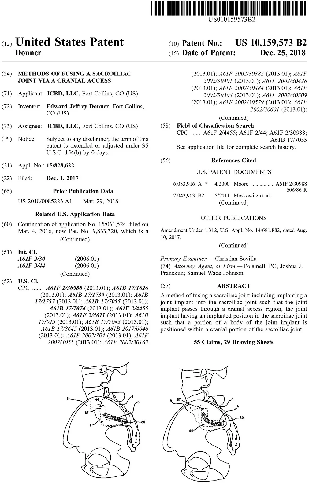
1. A method of fusing a sacroiliac joint defined between a sacrum and an ilium, the sacroiliac joint comprising an articular region that is generally L-shaped and comprising a cranial portion and a caudal portion, the cranial portion bounded at a superior end by an anterior-superior corner and a superior-posterior corner, the method comprising:
a) approaching the superior end of the articular region of sacroiliac joint with a joint implant comprising a body extending a length between a distal end and a proximal end; and
b) implanting the joint implant into the sacroiliac joint such that the joint implant passes through an access region defined between the anterior-superior corner and superior-posterior corner of the cranial portion of the articular region of the sacroiliac joint, the joint implant having an implanted position in the sacroiliac joint such that a portion of the body of the joint implant is positioned within the cranial portion of the sacroiliac joint.
2. The method of claim 1, wherein the body defines a generally planar member having a generally rectangular configuration, the body comprises a sacral face extending along the length, an iliac face extending along the length that is opposite the sacral face, a width between the sacral face and the iliac face being about a width of an implant receiving space defined between the sacrum and the ilium, a top surface extending between the sacral face and iliac face and extending along the length, a bottom surface opposite the top surface and extending between the sacral face and iliac face and extending along the length, and a height between the top surface and bottom surface being substantially greater than the width and being about a height of the implant receiving space defined between the sacrum and the ilium, the height of the implant receiving space extending generally within a joint plane of the sacroiliac joint and being generally perpendicular to the width of the implant receiving space, the length extending generally within the joint plane of the sacroiliac joint when the joint implant is in the implanted position within the sacroiliac joint, the length being generally perpendicular to both the width and the height of the body of the joint implant, and the length being substantially greater than both the width and the height of the body of the joint implant.
3. The method of claim 2, further comprising: c) inserting a guide wire into the sacroiliac joint; and d) advancing a cannulated probe having a distal spatulate portion over the guide wire and into the sacroiliac joint.
4. The method of claim 2, further comprising forming the implant receiving space by removing at least one of bone and cartilage from the sacrum, the ilium, or the sacroiliac joint prior to implanting the joint implant into the sacroiliac joint.
5. The method of claim 4, wherein the step of forming the implant receiving space comprises: aligning a drill jig comprising a plurality of drill guide holes such that at least one of the plurality of drill guide holes is generally coplanar with a joint plane of the sacroiliac joint; and drilling at least one bore into the sacroiliac joint through at least one of the plurality of drill guide holes so as to form the implant receiving space for the subsequent implantation of the joint implant.
6. The method of claim 4, wherein the step of forming the implant receiving space comprises: aligning a drill jig comprising a plurality of drill guide holes such that at least one of the plurality of drill guide holes is generally coplanar with a joint plane of the sacroiliac joint; and drilling at least one bore within the sacroiliac joint so as to remove an amount of the cartilage from within the sacroiliac joint.
7. The method of claim 4, wherein the step of forming the implant receiving space comprises: positioning a broach jig up to the sacroiliac joint, the broach jig comprising a broach guide hole configured to guide a broach into the sacroiliac joint; and advancing a distal end of a broach into the sacroiliac joint.
8. The method of claim 2, wherein the portion of the body of the joint implant that is positioned within the cranial portion of the sacroiliac joint is the proximal end.
9. The method of claim 8, wherein the distal end of the body of the joint implant is positioned generally inferiorly in the implanted position.
10. The method of claim 2, wherein, in implanting the joint implant into the sacroiliac joint, the bottom surface of the body of the joint implant is generally adjacent to a posterior border of the cranial portion.
11. The method of claim 2, wherein the distal end tapers to a terminal end.
12. The method of claim 2, wherein the body comprises a passageway extending between an opening on the sacral face and an opening on the iliac face.
13. The method of claim 12, further comprising inserting biocompatible material within the passageway.
14. The method of claim 1, wherein the body of the joint implant comprises an end cap having an end cap perimeter selected from at least one of a circle, oval, square, or rectangle configuration.
15. The method of claim 1, wherein the body of the joint implant further comprises an anti-migration element coupled to the proximal end.
16. The method of claim 15, wherein the anti-migration element comprises an enlarged terminal portion.
17. The method of claim 1, wherein the body of the joint implant further comprises a first planar member, a second planar member parallel with the first planar member, a third planar member, and a fourth planar member parallel with the third planar member, the first and second planar members being perpendicular to the third and fourth planar members, the first, the second, the third, and the fourth planar members extending the length.
18. The method of claim 1, wherein the body of the joint implant further comprises a bore extending therethrough, and the method further comprises: c) inserting a mechanical fastener through the bore and into the sacrum or the ilium.
19. The method of claim 18, wherein the bore extends through an anti-migration element of the joint implant.
20. A method of fusing a sacroiliac joint defined between a sacrum and an ilium, the sacroiliac joint comprising an articular region that is generally L-shaped and comprising a cranial portion and a caudal portion, the cranial portion bounded at a superior end by an anterior-superior corner and a superior-posterior corner, the method comprising:
a) approaching the superior end of the articular region of sacroiliac joint with a joint implant comprising a body extending a length between a distal end and a proximal end; and
b) implanting the joint implant non-transversely into the sacroiliac joint such that the proximal end of the body of the joint implant is positioned within the cranial portion of the sacroiliac joint, and the distal end of the body of the joint implant is positioned inferior to the proximal end.
21. The method of claim 20, wherein, in implanting the joint implant non-transversely into the sacroiliac joint, the joint implant passes through an access region defined between the anterior-superior corner and superior-posterior corner of the cranial portion of the articular region of the sacroiliac joint.
22. The method of claim 20, wherein the body defines a generally planar member having a generally rectangular configuration, the body comprises a sacral face extending along the length, an iliac face extending along the length that is opposite the sacral face, a width between the sacral face and the iliac face being about a width of an implant receiving space defined between the sacrum and the ilium, a top surface extending between the sacral face and iliac face and extending along the length, a bottom surface opposite the top surface and extending between the sacral face and iliac face and extending along the length, and a height between the top surface and bottom surface being substantially greater than the width and being about a height of the implant receiving space defined between the sacrum and the ilium, the height of the implant receiving space extending generally within a joint plane of the sacroiliac joint and being generally perpendicular to the width of the implant receiving space, the length extending generally within the joint plane of the sacroiliac joint when the joint implant is in the implanted position within the sacroiliac joint, the length being generally perpendicular to both the width and the height of the body of the joint implant, and the length being substantially greater than both the width and the height of the body of the joint implant.
23. The method of claim 21, further comprising: c) inserting a guide wire into the sacroiliac joint; and d) advancing a cannulated probe having a distal spatulate portion over the guide wire and into the sacroiliac joint.
24. The method of claim 21, further comprising forming an implant receiving space by removing at least one of bone and cartilage from the sacrum, the ilium, or the sacroiliac joint prior to implanting the joint implant into the sacroiliac joint.
25. The method of claim 24, wherein the step of forming the implant receiving space comprises: aligning a drill jig comprising a plurality of drill guide holes such that at least one of the plurality of drill guide holes is generally coplanar with a joint plane of the sacroiliac joint; and drilling at least one bore into the sacroiliac joint through at least one of the plurality of drill guide holes so as to form the implant receiving space for the subsequent implantation of the joint implant.
26. The method of claim 24, wherein the step of forming the implant receiving space comprises: aligning a drill jig comprising a plurality of drill guide holes such that at least one of the plurality of drill guide holes is generally coplanar with a joint plane of the sacroiliac joint; and drilling at least one bore within the sacroiliac joint so as to remove an amount of the cartilage from within the sacroiliac joint.
27. The method of claim 24, wherein the step of forming the implant receiving space comprises: positioning a broach jig up to the sacroiliac joint, the broach jig comprising a broach guide hole configured to guide a broach into the sacroiliac joint; and advancing a distal end of a broach into the sacroiliac joint.
28. The method of claim 22, wherein, in implanting the joint implant into the sacroiliac joint, the bottom surface of the body of the joint implant is generally adjacent to a posterior border of the cranial portion.
29. The method of claim 22, wherein the distal end tapers to a terminal end.
30. The method of claim 22, wherein the body comprises a passageway extending between an opening on the sacral face and an opening on the iliac face.
31. The method of claim 30, further comprising inserting biocompatible material within the passageway.
32. The method of claim 20, wherein the body of the joint implant comprises an end cap having an end cap perimeter selected from at least one of a circle, oval, square, or rectangle configuration.
33. The method of claim 20, wherein the body of the joint implant further comprises an anti-migration element coupled to the proximal end.
34. The method of claim 33, wherein the anti-migration element comprises an enlarged terminal portion.
35. The method of claim 20, wherein the body of the joint implant further comprises a first planar member, a second planar member parallel with the first planar member, a third planar member, and a fourth planar member parallel with the third planar member, the first and second planar members being perpendicular to the third and fourth planar members, the first, the second, the third, and the fourth planar members extending the length.
36. The method of claim 20, wherein the body of the joint implant further comprises a bore extending therethrough, and the method further comprises: c) inserting a mechanical fastener through the bore and into the sacrum or the ilium.
37. The method of claim 36, wherein the bore extends through an anti-migration element of the joint implant.
38. The method of claim 20, wherein the body of the joint implant further comprises a longitudinal axis, a first, a second, a third and a fourth member spaced apart around the longitudinal axis and joined with one another generally at the longitudinal axis, and wherein, in implanting the joint implant non-transversely into the sacroiliac joint, at least one member of the first, the second, the third, and the fourth members is positioned in the sacrum, and at least one member of the first, the second, the third, and the fourth members is positioned in the ilium.
39. The method of claim 38, wherein, in implanting the joint implant non-transversely into the sacroiliac joint, the first and the third members are positioned in the sacrum, and the second and the fourth members are positioned in the ilium.
40. The method of claim 20, wherein the body of the joint implant further comprises a first member, a second member parallel with the first member, a third member, and a fourth member parallel with the third member, and wherein, in implanting the joint implant non-transversely into the sacroiliac joint, the first and the third members are positioned in the sacrum, and the second and the fourth members are positioned in the ilium.
41. The method of claim 20, wherein the body of the joint implant further comprises a first planar member, a second planar member generally parallel with the first planar member, a third planar member, and a fourth planar member generally parallel with the third planar member, the first and the second planar members being at an angle relative to the third and the fourth planar members, the first, the second, the third, and the fourth planar members extending the length.
42. The method of claim 1, wherein the body of the joint implant further comprises a longitudinal axis, a first, a second, a third and a fourth member spaced apart around the longitudinal axis and joined with one another generally at the longitudinal axis, and wherein, in implanting the joint implant non-transversely into the sacroiliac joint, at least one member of the first, the second, the third, and the fourth members is positioned in the sacrum, and at least one member of the first, the second, the third, and the fourth members is positioned in the ilium.
43. The method of claim 42, wherein, in implanting the joint implant non-transversely into the sacroiliac joint, the first and the third members are positioned in the sacrum, and the second and the fourth members are positioned in the ilium.
44. The method of claim 1, wherein the body of the joint implant further comprises a first member, a second member parallel with the first member, a third member, and a fourth member parallel with the third member, and wherein, in implanting the joint implant non-transversely into the sacroiliac joint, the first and the third members are positioned in the sacrum, and the second and the fourth members are positioned in the ilium.
45. The method of claim 1, wherein the body of the joint implant further comprises a first planar member, a second planar member generally parallel with the first planar member, a third planar member, and a fourth planar member generally parallel with the third planar member, the first and the second planar members being at an angle relative to the third and the fourth planar members, the first, the second, the third, and the fourth planar members extending the length.
46. The method of claim 1, wherein the body of the joint implant further comprises a first planar member and a second planar member at an angle relative to and substantially non-parallel with the first planar member, the first and the second planar members extending the length.
47. The method of claim 20, wherein the body of the joint implant further comprises a first planar member and a second planar member at an angle relative to and substantially non-parallel with the first planar member, the first and the second planar members extending the length.
48. The method of claim 1, wherein, in implanting the joint implant into the sacroiliac joint, the joint implant does not enter the cranial portion through an extra-articular access region.
49. The method of claim 20, wherein, in implanting the joint implant into the sacroiliac joint, the joint implant does not enter the cranial portion through an extra-articular access region.
50. The method of claim 1, wherein the body of the joint implant further comprises a cylindrical volume extending the length.
51. The method of claim 50, wherein the body of the joint implant further comprises a generally planar member coupled with the cylindrical volume and extending the length.
52. The method of claim 51, wherein the cylindrical volume comprises an axial bore and a plurality of apertures arranged along the length extending from an exterior surface of the body into an inner portion of the cylindrical volume, and the generally planar member further comprises a passageway extending between apertures on opposite faces of the generally planar member, wherein a perimeter of the apertures on the opposite faces is substantially larger than a perimeter of each of the plurality of apertures extending into the inner portion of the cylindrical volume.
53. The method of claim 20, wherein the body of the joint implant further comprises a cylindrical volume extending the length.
54. The method of claim 53, wherein the body of the joint implant further comprises a generally planar member coupled with the cylindrical volume and extending the length.
55. The method of claim 54, wherein the cylindrical volume comprises an axial bore and a plurality of apertures arranged along the length extending from an exterior surface of the body into an inner portion of the cylindrical volume, and the generally planar member further comprises a passageway extending between apertures on opposite faces of the generally planar member, wherein a perimeter of the apertures on the opposite faces is substantially larger than a perimeter of each of the plurality of apertures extending into the inner portion of the cylindrical volume.