US PATENT 9,700,356 B2 SYSTEMS FOR AND METHODS OF FUSING A SACROILIAC JOINT
A sacroiliac joint fusion system including a joint implant, anchor element and delivery tool. The joint implant includes a bore extending non-parallel to the implant longitudinal axis. The anchor element is for receiving in the bore. The delivery tool includes an implant arm and anchor arm. The implant arm distal end is releasably coupled to the joint implant proximal end so the implant arm longitudinal axis is coaxial or parallel with the implant body longitudinal axis. An anchor arm distal end is engaged to the anchor element proximal end. The anchor arm is coupled to the implant arm such that the anchor element longitudinal axis is coaxially aligned with the bore longitudinal axis when the implant arm distal end is releasably coupled with the implant proximal end and the anchor arm distal end is engaged with the anchor element proximal end.
CLAIMS
What is claimed is:
1. A sacroiliac joint fusion system comprising:
a) a joint implant comprising: a longitudinal axis extending between a proximal end and a distal end of the joint implant; and a first bore extending non-parallel to the longitudinal axis;
b) an anchor element configured to be received in at least one of a sacrum or an ilium; and
c) a delivery tool comprising:
i) an implant arm comprising a shaft extending between a proximal end and a distal end of the implant arm and a handle at the proximal end, the distal end of the implant arm configured to releasably couple to the proximal end of the joint implant; and
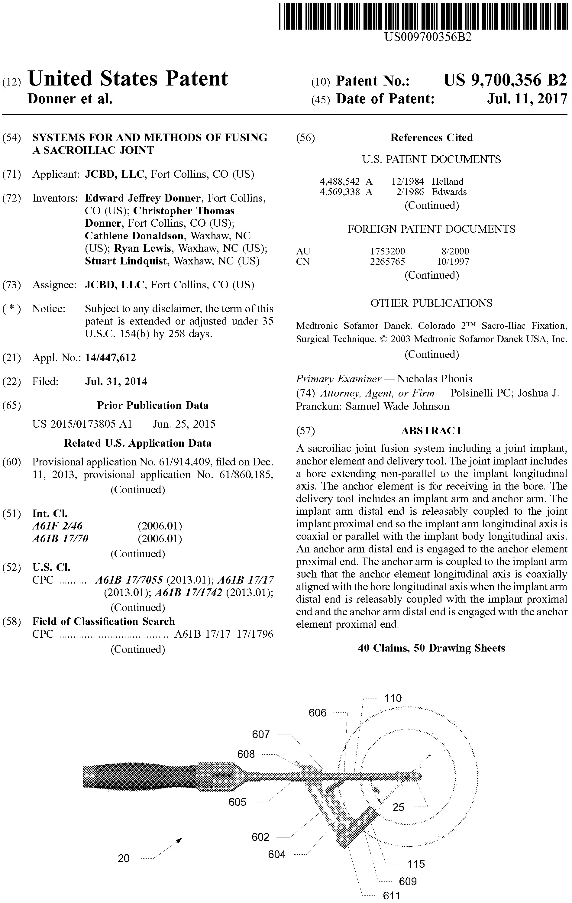
ii) an anchor arm comprising an anchor guide coupled to the implant arm via a distal articulating member and a proximal articulating member, the distal articulating member rotatably coupled with implant arm at a first end and rotatably coupled with the anchor guide at a second end, the proximal articulating member slidably coupled with the implant arm at a third end and configured to slidably translate distal-proximal along the shaft of the implant arm, the proximal articulating member rotatably coupled with anchor guide at a fourth end, the anchor guide configured to align the anchor element in a trajectory such that the anchor element will be received in the at least one of the sacrum or the ilium when the anchor element is guided by the anchor guide,
wherein, when the third end of the proximal articulating member is positioned in a proximal-most position, the anchor guide is configured to align the anchor element in the trajectory, and when the third end of the proximal articulating member is positioned in a distal-most position, the anchor guide is configured to align the anchor element in the trajectory.
2. The system of claim 1, wherein the first end is positioned distally of the third end on the implant arm.
3. The system of claim 2, wherein the second end is positioned distally of the fourth end on the anchor guide.
4. The system of claim 1, wherein the implant arm further comprises an actuation assembly that is configured to releasably couple and decouple with the joint implant.
5. The system of claim 1, wherein the actuation assembly is rotationally actuated.
6. The system of claim 1, wherein an angle of the trajectory relative to the longitudinal axis of the joint implant is different when the third end is in the proximal-most position and the distal-most position.
7. The system of claim 1, wherein, when the third end is in the proximal-most position, an angle between the trajectory and a longitudinal axis of the shaft of the implant arm is about 34 degrees.
8. The system of claim 1, wherein, when the third end is in the distal-most position, an angle between the trajectory and a longitudinal axis of the shaft of the implant arm is about 45 degrees.
9. The system of claim 1, wherein the first end of the distal articulating member includes a stop feature that inhibits rotation of the first end beyond a certain point.
10. The system of claim 9, wherein the stop feature is configured to contact the shaft of the implant arm when the third end of the proximal articulating member is in the proximal-most position.
11. The system of claim 1, wherein the joint implant comprises: an intraarticular element extending an implant length between the proximal and distal ends and further extending an implant height between an implant upper edge and an opposed implant lower edge, the intraarticular element comprising: a first articular face and an opposed second articular face extending the implant height and at least a portion of the implant length; the first bore formed within at least a portion of the intraarticular element and extending through the intraarticular element from the first articular face to the second articular face; and at least one keel attached to the intraarticular element along at least a portion of the implant length.
12. The system of claim 11, wherein each keel of the at least one keels projects perpendicularly outward from the first articular face and from the second articular face, ending in a first edge and a opposite second edge separated by a keel width.
13. The system of claim 12, wherein the first edge and the second edge are in parallel alignment along the implant length.
14. The system of claim 12, wherein the first edge and the second edge distally converge toward one another.
15. The system of claim 14, wherein the at least one keel comprises a first keel extending from the proximal end to the distal end, wherein the first keel is attached along the implant upper edge or the implant lower edge.
16. The system of claim 15, wherein the at least one keel further comprises a second keel extending from the proximal end to the distal end, wherein the second keel is attached along the implant upper edge or the implant lower edge opposite to the first keel.
17. The system of claim 16, wherein the keel width of the first keel is equal to the keel width of the second keel.
18. The system of claim 16, wherein the keel width of the first keel is larger than the keel width of the second keel.
19. The system of claim 11, wherein the at least one keel comprises a first keel extending from the proximal end to the distal end, wherein the first keel is attached to the intraarticular element between the implant upper edge and the implant lower edge.
20. The system of claim 17, wherein the first keel further comprises a keel gap extending over an intersection of the first keel with the first bore.
21. The system of claim 11, wherein the first bore extends through the intraarticular element along a bore axis forming an angle ranging from about 45 degrees to about 90 degrees relative to a plane parallel to the first articular face or the second articular face.
22. The system of claim 11, wherein the first bore further comprises a bore length extending along a portion of the implant length, the portion ranging from about 40% to about 70% of the implant length.
23. The system of claim 22, wherein the bore length is situated between the proximal end and the distal end.
24. The system of claim 23, wherein one end of the bore length is coincident with the distal end.
25. The system of claim 11, wherein the anchor passes through the first bore.
26. The system of claim 11, wherein the anchor passes outside of the implant above the upper edge or below the lower edge.
27. The system of claim 11, wherein the intraarticular element further comprises: a proximal face situated at the implant proximal end; and a threaded bore extending from the proximal face along the implant length toward the distal end and opening distally into the first bore.
28. The system of claim 11, wherein the at least one keel and the intraarticular element taper distally into a distal edge situated at the distal end.
29. The system of claim 11, wherein the implant length ranges from about 20 mm to about 50 mm.
30. The system of claim 11, wherein the implant height ranges from about 10 mm to about 20 mm.
31. The system of claim 11, wherein an intraarticular thickness between the first articular face and the second articular face ranges from about 5 mm to about 7 mm.
32. The system of claim 12, wherein the keel width ranges from about 10 mm to about 20 mm.
33. The system of claim 1, wherein the anchor element is configured to avoid contact with the joint implant when aligned in the trajectory.
34. The system of claim 1, wherein the anchor element will be received within the first bore when the anchor element is guided by the anchor guide along the trajectory.
35. A sacroiliac joint fusion system comprising:
a) a joint implant comprising a body;
b) an anchor element configured to be received in at least one of a sacrum or an ilium; and
c) a delivery tool comprising:
i) an implant arm comprising a shaft extending between a proximal end and a distal end of the implant arm, the distal end of the implant arm configured to releasably couple to the joint implant; and
ii) an anchor arm comprising an anchor guide coupled to the implant arm, the anchor guide being articulable relative to the implant arm between pre-set orientations that are configured to align the anchor element in pre-set trajectories relative to the joint implant, wherein the anchor element is configured to be received in the at least one of the sacrum or the ilium while avoiding contact with the joint implant when the anchor element is guided by the anchor guide in the pre-set trajectories, wherein the anchor guide is coupled to the implant arm via a distal articulating member and a proximal articulating member, the distal articulating member rotatably coupled with implant arm at a first end and rotatably coupled with the anchor guide at a second end, the proximal articulating member slidably coupled with the implant arm at a third end and configured to slidably translate distal-proximal along the shaft of the implant arm, the proximal articulating member rotatably coupled with anchor guide at a fourth end.
36. The system of claim 35, wherein, when the third end of the proximal articulating member is positioned in a proximal-most position, the anchor guide is configured to align the anchor element in a first trajectory of the pre-set trajectories, and when the third end of the proximal articulating member is positioned in a distal-most position, the anchor guide is configured to align the anchor element in a second trajectory of the pre-set trajectories.
37. The system of claim 36, wherein an angle between the first trajectory and a longitudinal axis of the shaft of the implant arm is about 34 degrees.
38. The system of claim 36, wherein, when the third end is in the distal-most position, an angle between the second trajectory and a longitudinal axis of the shaft of the implant arm is about 45 degrees.
39. The system of claim 36, wherein the first end of the distal articulating member includes a stop feature that inhibits rotation of the first end beyond a certain point.
40. The system of claim 39, wherein the stop feature is configured to contact the shaft of the implant arm when the third end of the proximal articulating member is in the proximal-most position.