US PATENT 11,877,931
Sacropelvic Fusion Implant System for Providing a Foundation for Spinopelvic Fixation Constructs in Adult Spinal Deformity Surgery
A method of surgically treating a patient suffering from severe pain and disability of the low back and buttock by stabilizing the patient's spinal column to their pelvis with an implant system including surgical tools and an implant designed to prevent movement between the sacrum and the ilium while being able to attach to a spinal fusion rod which connect to pedicle screws implanted in the bones of the spine of the patient in order to offer lasting relief of the patient's symptoms. The system is designed to address complications in adult spinal deformity by optimizing spinopelvic fixation via-a-vis the unique biomechanics of the SI joint. The sacropelvic system is a surgical solution which provides an additively manufactured implant at the base of the spine employing an S2AI trajectory while utilizing assisting technologies including surgical navigation and intraoperative neurophysiological monitoring.
CLAIMS
1. A method for stabilizing a vertebra and a pelvic region comprising a sacrum, an ilium, and a sacroiliac joint of a patient, the method comprising:
delivering an anchor into the pelvic region along a posterior sacral alar-iliac (“SAI”) trajectory such that the anchor enters a sacral ala, crosses the sacroiliac joint, and enters the ilium;
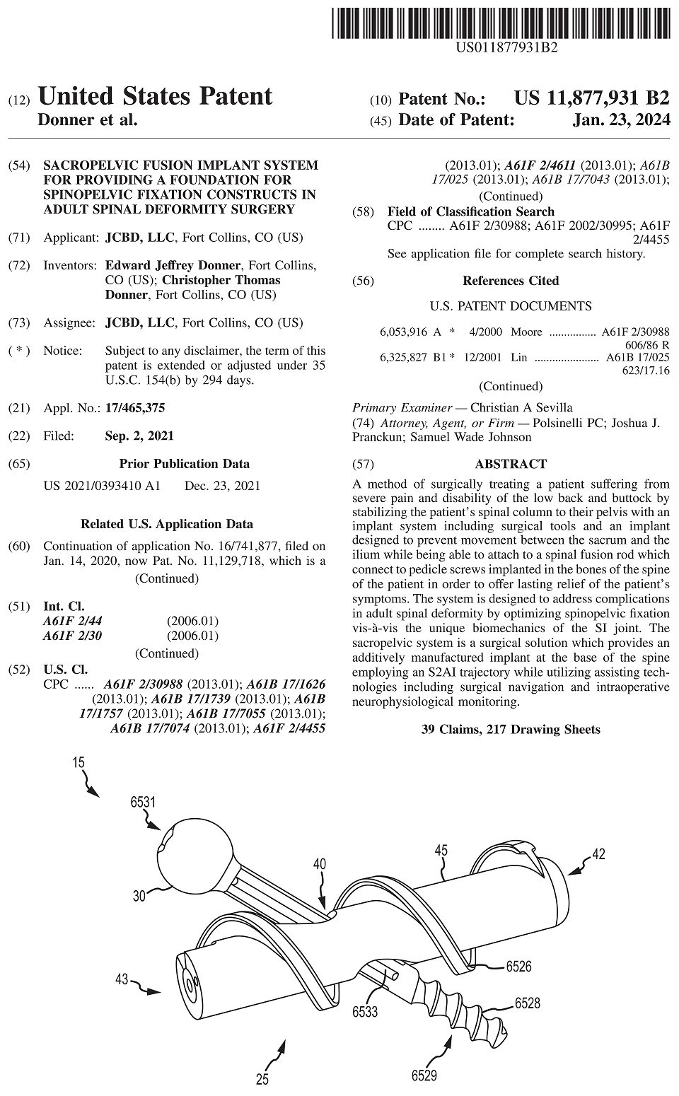
implanting an implant into the pelvic region such that the implant engages the sacrum, the sacroiliac joint and the ilium, the implant comprising a distal end, a proximal end, a longitudinal axis extending between the distal and proximal ends, an implant body extending a length between the distal and proximal ends, a first thread defined on an exterior surface of the implant body, and an anchor bore defined in the implant body and comprising a bore axis, wherein, in an implanted configuration, the anchor bore axis is coaxial with the SAI trajectory and the anchor is located within the anchor bore of the implant body so as to form a composite implant;
attaching a rod of a spinal support system to the composite implant; and
stabilizing the vertebra and the pelvic region by forming a construct comprising the composite implant, and the rod of the spinal support system.
2. The method of claim 1, wherein the implant body comprises interconnected pores.
3. The method of claim 1, wherein the posterior SAI trajectory is a posterior second sacral alar-iliac (“S2AI”) trajectory.
4. The method of claim 1, wherein the anchor bore extends transversely to the longitudinal axis of the implant.
5. The method of claim 1, wherein the anchor includes a threaded distal end.
6. The method of claim 5, wherein, in the implanted configuration, the threaded distal end is positioned outside the anchor bore of the implant body.
7. The method of claim 6, wherein the anchor further includes a non-threaded portion that is proximal to the threaded distal end, the non-threaded portion being positioned within the anchor bore of the implant body when the anchor and the implant body are in the implanted configuration.
8. The method of claim 1, further comprising attaching a head portion to the composite implant, the head portion configured to secure the rod.
9. The method of claim 1, wherein the implant is additively manufactured.
10. The method of claim 1, wherein the implant is implanted non-transversely into the sacroiliac joint.
11. A method for stabilizing a vertebra and a pelvic region comprising a sacrum, an ilium, and a sacroiliac joint of a patient, the method comprising:
delivering an anchor into the pelvic region along a posterior sacral alar-iliac (“SAI”) trajectory such that the anchor enters a sacral ala, crosses the sacroiliac joint, and enters the ilium, the anchor comprising a distal anchor end, a proximal anchor end, an anchor longitudinal axis extending between the distal anchor and proximal anchor ends, an anchor body extending a first length between the distal anchor and proximal anchor ends, a distal iliac bone anchoring region, and a first interface feature on the anchor body that is proximal to the distal iliac bone anchoring region;
implanting an implant into the pelvic region such that the implant engages the sacrum, the sacroiliac joint and the ilium, the implant comprising a distal implant end, a proximal implant end, an implant longitudinal axis extending between the distal implant and proximal implant ends, an implant body extending a second length between the distal implant and proximal implant ends, and an anchor bore defined in the implant body and comprising a bore axis, the anchor bore comprising a second interface feature configured to interface with the first interface feature of the anchor, the implant body comprising a bone growth region, wherein, in an implanted configuration, the anchor bore axis is oriented and positioned coaxially with the SAI trajectory and the anchor is located within the anchor bore of the implant body so as to form a composite implant and wherein the first and second interface features define an interface arrangement that is configured to limit a movement between the anchor and the implant in the implanted configuration;
attaching a rod of a spinal support system to the composite implant; and
stabilizing the vertebra and the pelvic region by forming a construct comprising the composite implant, and the rod of the spinal support system.
12. The method of claim 11, wherein the interface arrangement comprises complementary threaded surfaces.
13. The method of claim 11, wherein the interface arrangement comprises complementary surfaces configured to provide a virtual cold weld between the anchor and the implant upon forming the composite implant.
14. The method of claim 11, wherein the first interface feature includes a portion on the body of the anchor having a non-circular cross section and wherein the second interface feature includes a portion on an interior wall of the anchor bore comprising a non-circular cross section.
15. The method of claim 11, wherein the implant body further includes a rectilinear cross-section transverse to the implant longitudinal axis.
16. The method of claim 11, wherein the bone growth region of the implant body comprises interconnected pores.
17. The method of claim 11, wherein the posterior SAI trajectory is a posterior second sacral alar-iliac (“S2AI”) trajectory.
18. The method of claim 11, wherein the anchor bore extends transversely to the implant longitudinal axis.
19. The method of claim 11, wherein the anchor includes a threaded distal end at the distal iliac bone anchoring region.
20. The method of claim 19, wherein, in the implanted configuration, the threaded distal end is positioned outside the anchor bore of the implant body.
21. The method of claim 20, wherein the anchor further includes a non-threaded portion that is proximal to the threaded distal end, the non-threaded portion being positioned within the anchor bore of the implant body when the anchor and the implant body are in the implanted configuration.
22. The method of claim 11, further comprising attaching a head portion to the composite implant, the head portion configured to secure the rod.
23. The method of claim 11, wherein the bone growth region of the implant body comprises a plurality of struts that define a plurality of openings extending therein.
24. The method of claim 11, wherein the bone growth region of the implant body comprises:
an exterior surface extending the second length;
an interior surface opposite the exterior surface and extending the second length, the interior surface defining an internal volume therein;
a wall thickness defined between the external surface and the interior surface;
a first wall section comprising a first plurality of struts arranged along the second length and defining a first plurality of openings extending through the wall thickness; and
a second wall section comprising a second plurality of struts arranged along the second length and defining a second plurality of opening extending through the wall thickness,
wherein the first and second plurality of struts are each arranged along lengths of the first and second wall sections, respectively, in a repeating strut pattern.
25. The method of claim 24, wherein the first and second wall sections are generally planar.
26. The method of claim 24, wherein the exterior surface includes a polygonal cross-section transverse to the second length.
27. The method of claim 24, wherein the repeating strut pattern defines at least two openings that are arranged in a mirror image fashion relative to each other.
28. The method of claim 24, wherein the repeating strut pattern of the first and second plurality of struts, respectively, are identical to each other.
29. The method of claim 24, wherein the first and second wall sections are generally parallel to each other.
30. The method of claim 24, wherein each of the first and second wall sections comprises anti-migration surface features on the exterior surface.
31. The method of claim 24, wherein each opening of the first and second plurality of openings is generally polygonal in shape.
32. The method of claim 24, wherein the implant is implanted non-transversely into the sacroiliac joint.
33. The method of claim 11, wherein the movement is rotation.
34. The method of claim 11, wherein the first interface feature on the anchor body includes one of outward extending splines or inward extending grooves, and the second interface feature on anchor bore of the implant body includes the other of outward extending splines or inward extending grooves.
35. The method of claim 1, wherein the implant is implanted into the pelvic region prior to the anchor being delivered into the pelvic region.
36. The method of claim 1, wherein the first thread of the implant body of the implant includes a first thread pitch, the anchor includes a second thread defined thereon, the second thread of the anchor including a second thread pitch that is different than the first thread pitch.
37. The method of claim 11, wherein the implant is implanted into the pelvic region prior to the anchor being delivered into the pelvic region.
38. The method of claim 11, wherein the implant body further includes a first thread defined on an exterior surface of the implant body, the first thread includes a first thread pitch, and wherein the anchor includes a second thread defined thereon, the second thread of the anchor including a second thread pitch.
39. The method of claim 38, wherein the second thread pitch is different than the first thread pitch.